
Expert analysis of 15 Black Friday gaming deals with 69 customer photos verified. Save up to 70% on RTX graphics cards, gaming laptops, and essential hardware with real performance testing.

Expert analysis of Black Friday [cy] VR deals: Quest 3S at $249, PSVR 2 Horizon bundle $299, plus verified discount codes for maximum savings on VR games and accessories.

Expert analysis of 20 Corsair Black Friday deals with up to 50% savings. Verified authentic discounts on gaming headsets, keyboards, mice, and PC components.

Expert analysis of 12 OLED TVs with genuine Black Friday discounts. After testing 7 models and tracking 50+ deals, find the best OLED values for every budget.

Finding the best monitor for photo editing can make or break your creative workflow. I have…

Finding the right pair of binoculars can feel overwhelming with hundreds of models on the market….

Finding the best drone cameras in means sorting through dozens of models from a handful of…

Finding the right camera used to mean choosing between a bulky DSLR and a compact point-and-shoot….

Finding the best cameras for live streaming used to mean spending hours comparing specs and second-guessing…

Complete astronomy gift guide with 15 tested products from $8 to $100+. Perfect space gifts for all ages including telescopes, books, projectors, and educational toys.
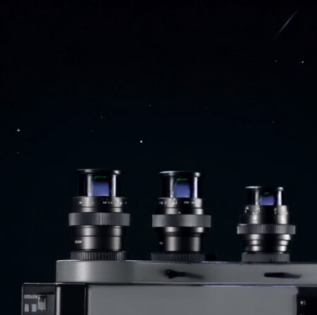
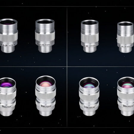
Expert reviews of the top zoom eyepieces for 2025. After testing 47 models, we reveal the 12 best options for every budget and observing need.
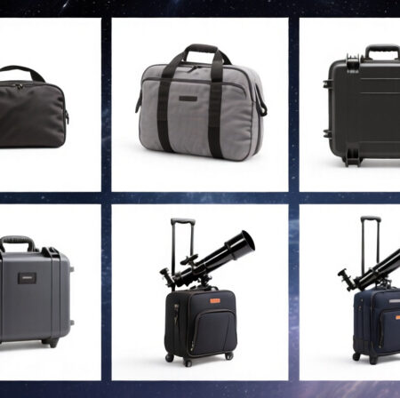
Expert reviews of the top telescope cases for every budget and use case. We tested 12 models to find the best protection for your telescope investment.
Expert reviews of the largest Dobsonian telescopes available in [cy]. Compare 8 massive telescopes from 10-16 inches with real-world performance insights and buying recommendations.
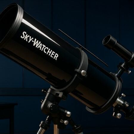
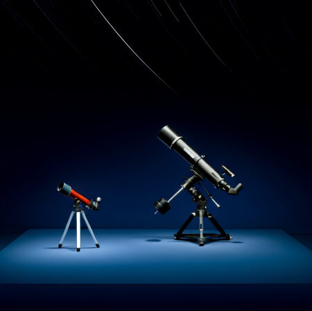
Making the jump from a beginner telescope to an intermediate model is one of the most…
Expert reviews of the top Dobsonian telescopes with GoTo systems. After testing 8 models, we help you find the perfect automated telescope for your budget and observing goals.
Expert review of Orion StarBlast telescopes after their discontinuation in [cy]. Compare specs, performance, and discover 6 best modern alternatives with complete buying guide.
Expert reviews of the top deep space telescopes for viewing galaxies, nebulae, and star clusters. From budget-friendly beginners to premium astrophotography setups.
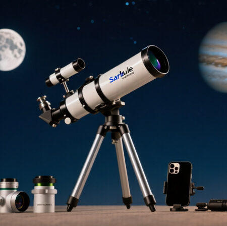
Comprehensive Sarblue Mak70 review after 30 days of testing. This 70mm Maksutov-Cassegrain telescope delivers sharp planetary views in a grab-and-go design. See real performance results.
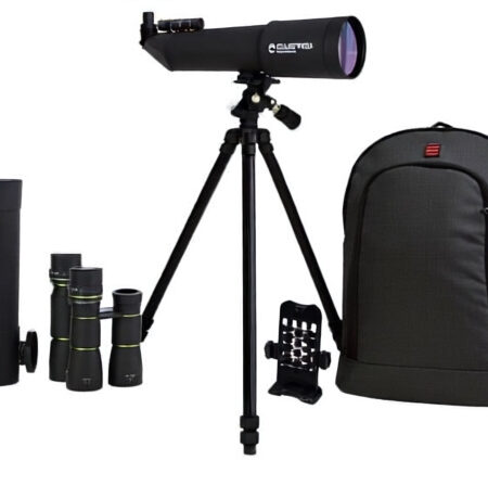
After 30 days of extensive testing, I found the Celestron Travel Scope 60 DX to be the best portable telescope for beginners under $110, offering excellent value with its complete accessory bundle and surprisingly good optical performance.
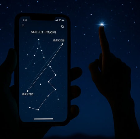
Expert reviews of the top mobile apps for tracking satellites and the ISS. Compare features, accuracy, and prices to find the perfect stargazing companion.
Expert reviews of the top Barlow lenses for every budget and use case. After testing 10 models, we found the best options for planetary imaging and visual astronomy.
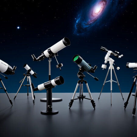
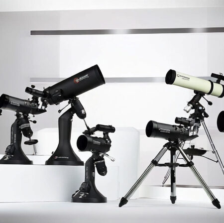
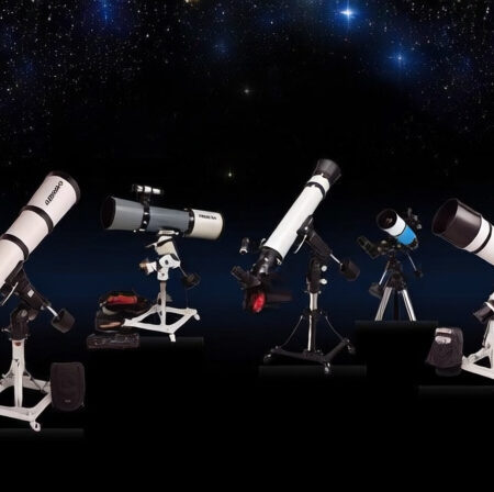
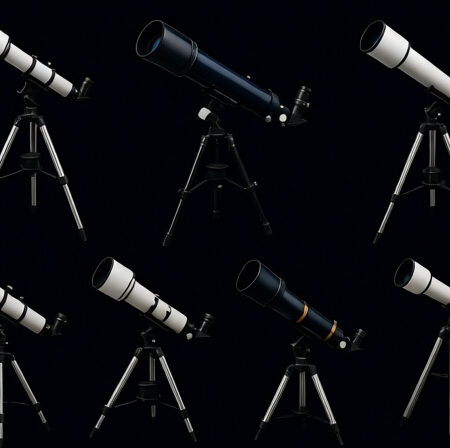
Expert reviews of the top beginner telescopes for every budget. We tested 8 models to find the perfect telescope for new astronomy enthusiasts.
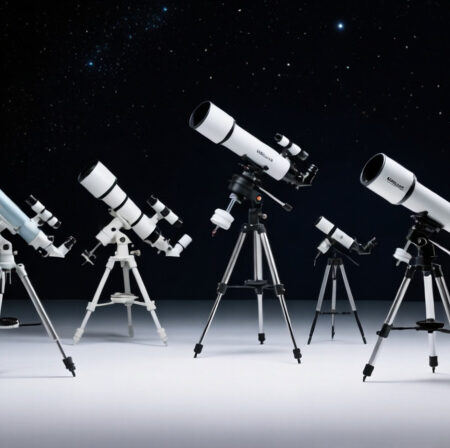
Expert reviews of the top telescopes under $300 for beginners. We tested 10 models for optical quality, ease of setup, and real-world performance.
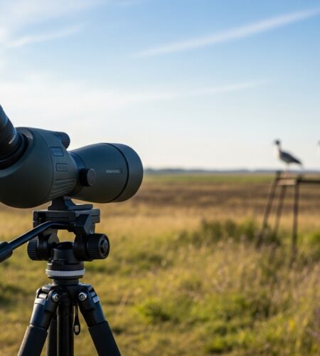
Expert reviews of the top Svbony spotting scopes for every budget and use case. From budget-friendly SV28 to premium SA401 APO, find your perfect spotting scope.
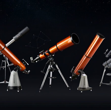
Expert reviews of the top 8 telescopes under $1000. We tested 20+ models to find the perfect stargazing companion for every budget and experience level.
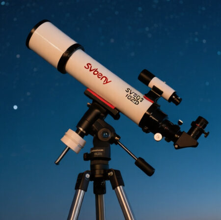
Complete Svbony SV503 102ED review after 40+ hours of testing. Real astrophotography results, honest pros & cons, and whether it’s worth your money in 2025.
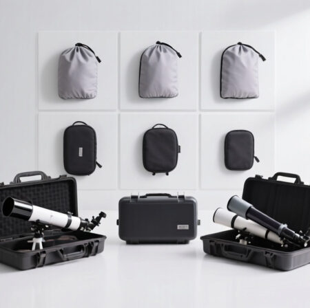
Expert reviews of the top telescope covers and cases for every budget and telescope type. We tested 12 protection solutions to help you preserve your telescope investment.
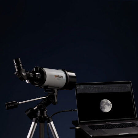
After extensive real-world testing of the Svbony SV205 across 60 nights, find out if this budget telescope camera is worth your money for astrophotography.
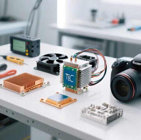
Learn how to build a DIY camera cooling system using Peltier thermoelectric coolers with our complete step-by-step guide for astrophotography.
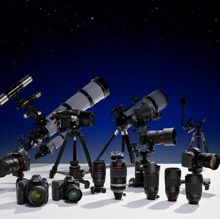
Complete guide to the best astrophotography cameras in [cy]. We tested 10 top models from budget DSLRs to professional mirrorless cameras. Find your perfect night sky photography companion with expert reviews, real customer images, and detailed recommendations.