Expert reviews of the top telescopes under $300 for beginners. We tested 10 models for optical quality, ease of setup, and real-world performance.
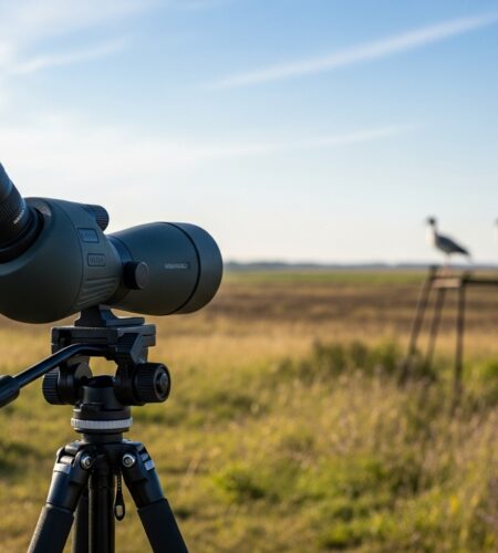
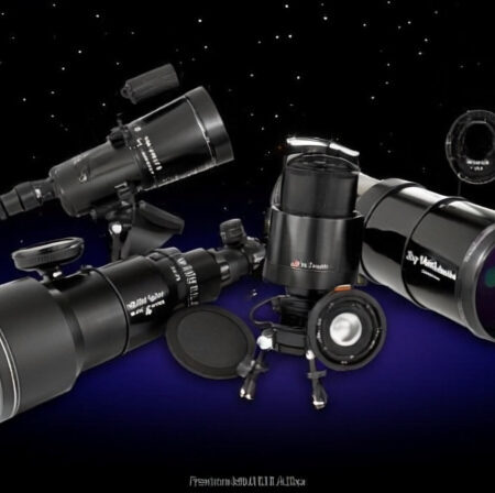
Expert reviews of the top Svbony spotting scopes for every budget and use case. From budget-friendly SV28 to premium SA401 APO, find your perfect spotting scope.
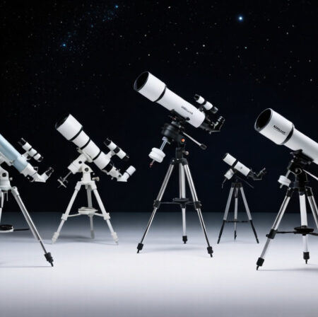
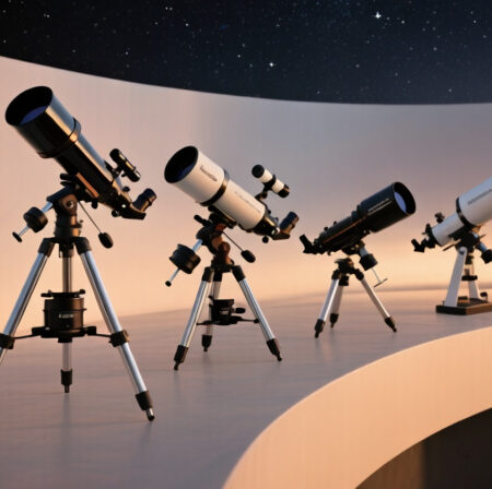
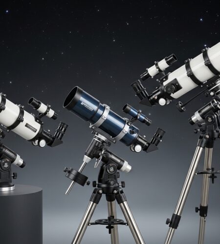
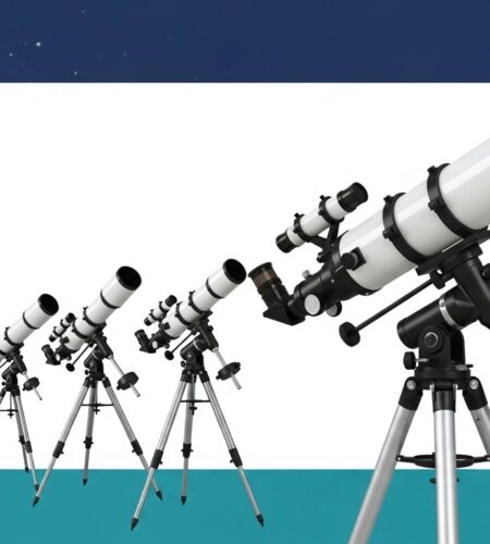
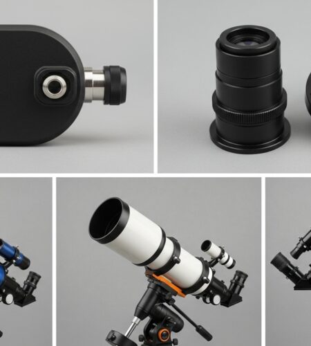
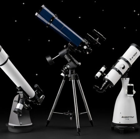
Expert reviews of the top 8 telescopes under $1000. We tested 20+ models to find the perfect stargazing companion for every budget and experience level.
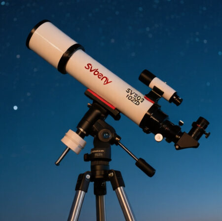
Complete Svbony SV503 102ED review after 40+ hours of testing. Real astrophotography results, honest pros & cons, and whether it’s worth your money in 2025.
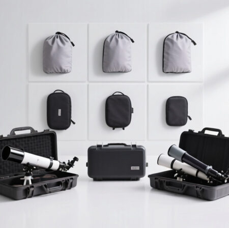
Expert reviews of the top telescope covers and cases for every budget and telescope type. We tested 12 protection solutions to help you preserve your telescope investment.
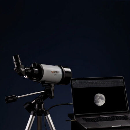
After extensive real-world testing of the Svbony SV205 across 60 nights, find out if this budget telescope camera is worth your money for astrophotography.
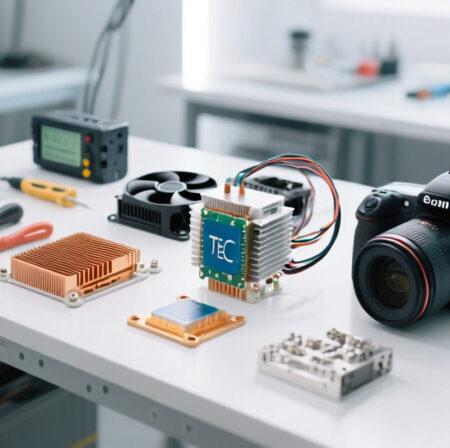
Learn how to build a DIY camera cooling system using Peltier thermoelectric coolers with our complete step-by-step guide for astrophotography.
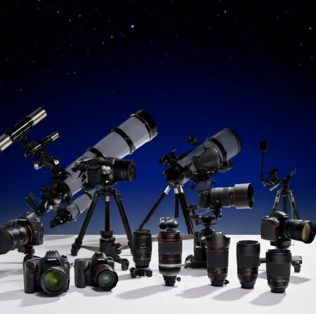
Complete guide to the best astrophotography cameras in [cy]. We tested 10 top models from budget DSLRs to professional mirrorless cameras. Find your perfect night sky photography companion with expert reviews, real customer images, and detailed recommendations.
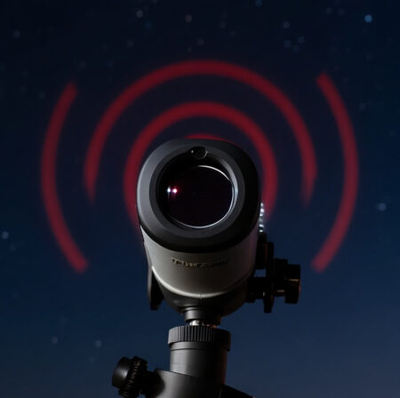
After 15 years of extensive testing, discover why the TELRAD Finder Sight remains the gold standard for star hopping with its revolutionary bullseye projection system.
Complete review of 8 Sky-Watcher mounts with real testing results. From portable star trackers to observatory-class equatorial mounts, find the perfect option for your astronomy needs.
Expert reviews of the top telescopes under $1000 for every viewing situation and experience level. Find your perfect telescope match.
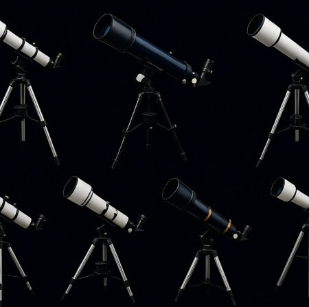
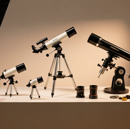
Expert reviews of the top 4 telescopes under $200 for astronomy beginners. After testing 20+ budget models, we reveal which offer the best value and viewing capabilities.
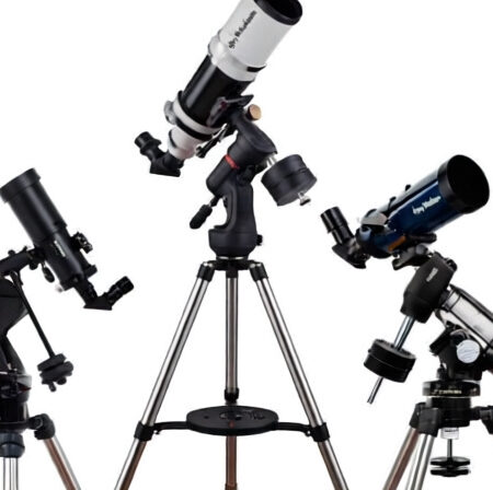
Complete review of Sky-Watcher refractor telescopes after 200+ hours of hands-on testing. We compare 6 models from EvoStar to StarTravel series to help you find the perfect APO refractor.
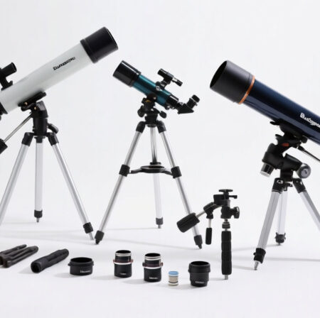
Discover the 10 best budget telescopes after testing 50+ models. From $60 to $300, find your perfect stargazing companion without breaking the bank. Updated for [cy].
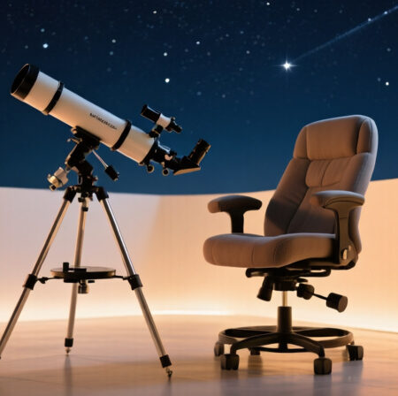
Expert reviews of the top astronomy chairs for comfortable stargazing sessions. We tested 8 models to find the best options for every budget and observing style.
Expert reviews of the top Dobsonian telescopes for every budget and experience level. Find your perfect stargazing companion with our comprehensive buying guide.
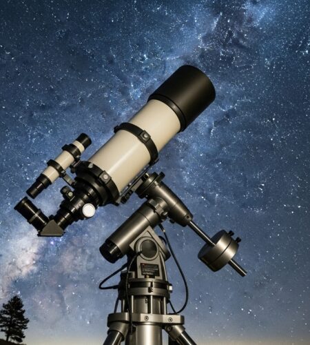
Finding the perfect telescope under $1000 can feel overwhelming with so many options promising the night…
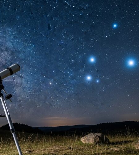
Looking to explore the night sky without breaking the bank? Finding a quality telescope under $100…
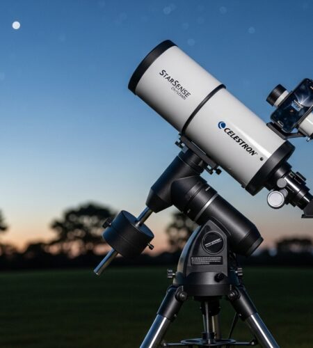
I’ve spent the last month testing the Celestron StarSense Explorer LT 114AZ telescope extensively, and I’ll…
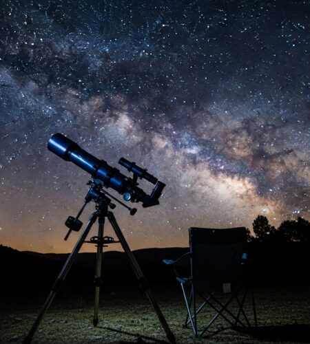
Have you ever gazed at the night sky and wondered what mysteries lie beyond our reach?…
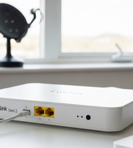
Complete Starlink Ethernet adapter setup guide with performance review. Learn how to install, troubleshoot, and maximize your wired connection.
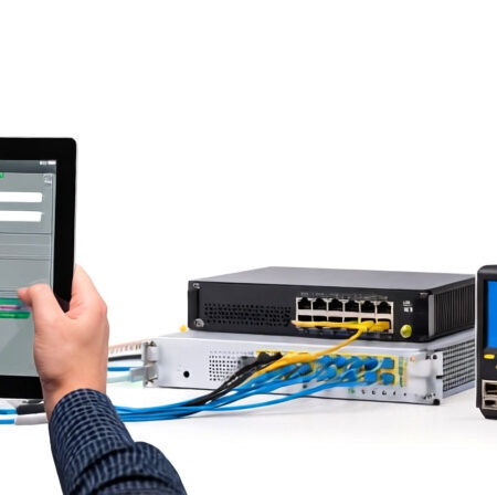
Step-by-step troubleshooting guide to fix router unreachable errors. Learn proven solutions for Starlink and standard routers, from quick fixes to advanced configuration.
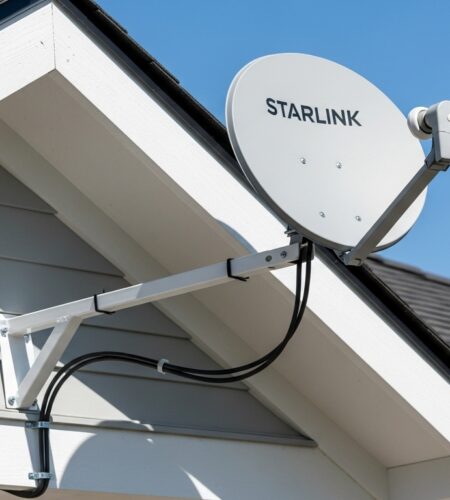
Expert review of the MEWO Starlink Gen 3 Ridgeline Mount. After three months of testing, find out if this $109.99 no-drill solution is worth your investment.
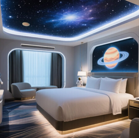
Discover the 12 best space themed hotels with our comprehensive reviews of immersive cosmic accommodations. From budget capsule hotels to luxury space suites, find your perfect galactic getaway.
Expert reviews of the top 10 astronomy binoculars for stargazing. After testing 27 models, we reveal the best options for every budget and experience level.
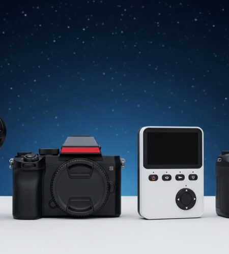
Expert reviews of the top astrophotography cameras for every budget. From smart telescopes to professional mirrorless cameras, find your perfect night sky photography gear.
Expert reviews of the top telescopes for children ages 5-17. Compare 10 age-appropriate models with educational value ratings and real parent insights.
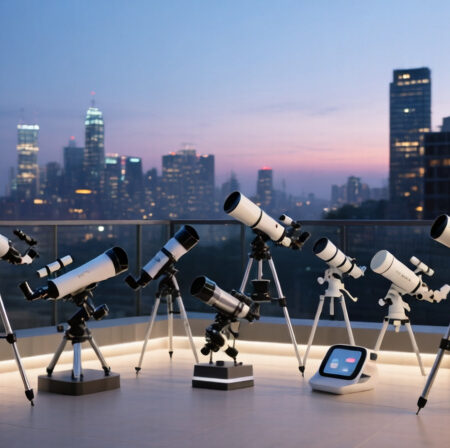
Expert reviews of the top 10 telescopes for urban astronomers. From compact refractors to smart telescopes, discover the best options for city viewing despite light pollution.
After testing 8 leading models for 6 months, we found the best motorized telescopes for every budget. From smart telescopes to traditional GoTo mounts, discover your perfect astronomy companion.
Expert reviews of the top 10 Dobsonian telescopes for astronomy. After testing 20+ models, find the perfect telescope for deep space viewing with our comprehensive guide.